


Next: Simulation
Up: FAST ORBIT FEEDBACK
Previous: Theoretical Concepts
The SLS storage ring is partitioned in 12 sectors containing 6 monitors and 6 correctors per plane. Figure 4 illustrates the partitioning of the inverse response matrix. Corresponding submatrices are distributed to the sectors in order to determine their corrector settings based on their monitor readings. Obviously there must be the possibility to get monitor and matrix information from the adjacent sectors to cover correctors close to the edges of a sector. This can be implemented by means of dedicated links between adjacent sectors. The result is a ``leap frog'' link structure around the machine (see Figure 4).
Figure 4:
Schematic view of the inverse of the response matrix partitioned into 12 sectors (black boxes) containing 6 monitors and 6 correctors each. The principle layout of the proposed ``leap frog'' link structure between sectors is shown on the right side.
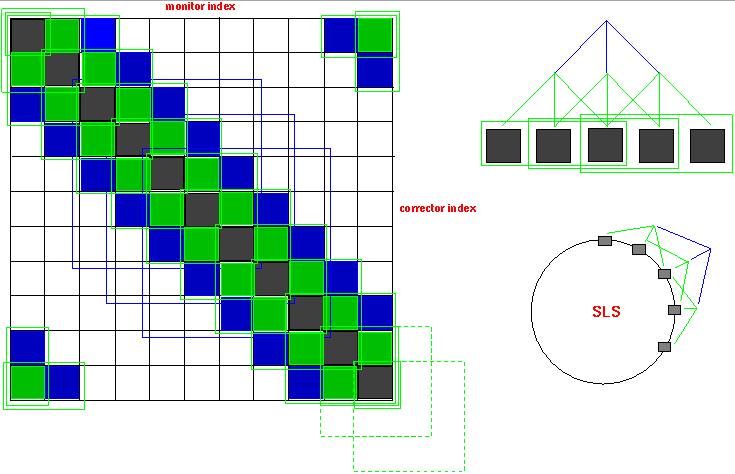 |
Figure 5:
Schematic view of the implementation of the fast orbit feedback
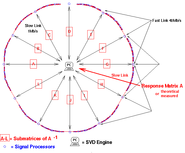 |
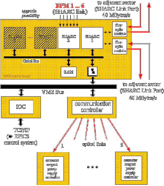
Figure 5 shows a schematic view of the implementation of the feedback. A central unit named ``SVD Engine'' performs the SVD based response matrix inversion and distributes the submatrices. All subsequent matrix operations are then performed in parallel by the individual sectors. Only if the corrector-monitor set changes the inverted matrix has to be recalculated by the ``SVD Engine''. This solution requires local intelligence within the sectors. The necessary computing power is delivered by special signal processor boards which are integral part of the proposed digital monitor system [1]. The links are based on protocol free unidirectional data connections transfering data at a rate of 40 Mb/sec (see Figure 6 for details). It should be noted that additional monitors at the location of the insertion devices can be easily added to the feedback.
Figure 6:
Layout of the fast orbit feedback electronics
 |
Next: Simulation
Up: FAST ORBIT FEEDBACK
Previous: Theoretical Concepts
Michael Boege
1999-06-07