 |
|
|||||||||
|---|---|---|---|---|---|---|---|---|---|---|
|
Updated: 21.12.2012 |
The Linac
Explanation of the linac components
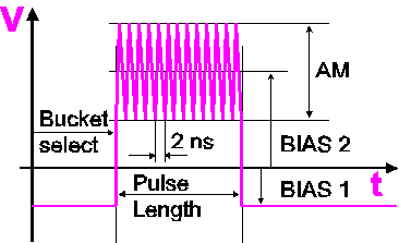
Electron GunThe gun is a triode consisting of cathode, grid and anode. The electrons are emitted from the thermionic barium dispenser cathode and accelerated by the 90 kV anode voltage. Primal time structure and charge of the beam is controlled by the voltage of the grid, shown here relativ to cathode potential for operation in multibunch mode: A 500 MHz oscillation is applied for 200-900~nsec duration ( = pulse length) to generate a train of 100-450 bunches for filling the corresponding RF buckets of the booster: Since the booster operates at 500 MHz, the distance between bunches is 2 nsec. In single bunch mode, a single burst of approx. 1 nsec duration is applied to generate one strong bunch for a single booster bucket. In both cases these modulations are repeated at 3 Hz. A negative DC offset (BIAS1) prohibits emission from the cathode between pulses, a rectungalar pulse (BIAS2) enables emission and the superimposed amplitude AM applies the 500 MHz modulation. An initial delay (bucket select) selects the bucket where the train starts.
Subharmonic Pre-BuncherThe pre-buncher operates at 500 MHz and has the purpose to increase the modulation depth from the gun, i.e. to compress the bunches:
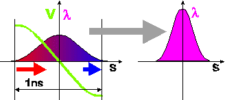
Particles arriving too early are decelerated, particles arriving too late are accelerated. Since the beam is not yet high-relativistic a velocity dispersion is introduced, the late particles catch up, the early particles slow down and thus the bunch is compressed after some drift space.
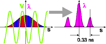
Pre-buncherThe pre-buncher operates at 3 GHz like the accelerating sections. Its task is to create a 3 GHz modulation (which would be a too high frequency for the gun grid modulation) in order to make the beam acceptable for the 3 GHz wave of the accelerating structures. Thus it "chops" the 1 nsec bunch from the subharmonic buncher into 3 smaller bunches separated by 0.33 nsec:
The actions on the beam from SPB and PBU superimpose and turn the initial 1 nsec gun pulse into approx. three 3 GHz pulses whith enhancement of the central pulse on expense of the leading and trailing pulses.
Final buncherThe final buncher also operates at 3 GHz and has the purpose to increase the modulation depth from the prebuncher, i.e. to further compress the bunches like the subharmonic prebuncher did for the bunches coming from the gun. At the same time it also accelerates the beam to approx. 4 MeV in order to "freeze" the time structure due to higher relativistic motion. Actually the final buncher is working both as buncher and as accelerating section, however it is always optimized for optimum bunching giving smallest possible energy spread and not for highest acceleration since the latter is taks of the accelerating sections.
Accelerating sectionsThe two identical accelerating sections accelerate the beam while not changing its time structure anymore. 50 MeV are reached after the first section and 100 MeV after the second. Usually the voltage of the second section is used for adjustment of the beam energy.
SolenoidsThe 16 solenoids form a magnetic channel to focus the beam and counteract space charge effects. A complex interplay of space charge, chromatic effects, RF fields and magnetic forces finally gives the transverse emittances of the beam. Setting up the solenoids is a difficult task to be done by experts exclusively. Pratically in routine operation well-tried solenoid currents are downloaded once in the beginning and never changed during the shift.
QuadrupolesThe quadrupole triplet between the sections provides full transmission through the second section and suitable beam transverse beam parameters at the exit in order to give the subsequent transferline a handle to shape the beam for matching into the booster.
[BACK]
|
||